What is Conductivity?
Conductivity (or specifically electrolytic conductivity) is the ability of a substance to conduct electric current. It is the reciprocal of the more common term, resistivity. All substances possess conductivity to some degree, but the amount varies widely, ranging from extremely low (insulators such as benzene, and glass) to very high (silver, copper, and metals in general). Most industrial interest is in the conductivity measurement of liquids. Electric current will readily flow through some liquids. The less ordered arrangement of the liquid molecules is not conducive to free electron movement. Therefore, another sort of charged particle must serve this purpose if any current is to flow at all.
In solvents where electrical conductance occurs, notably in water, ionization will provide the needed carriers. Ionization refers to the tendency of most soluble inorganic compounds to partially or completely separate into two or more elemental components, called ions, having opposite electrical charges. Moreover, these charged particles, or ions, act as current carriers producing electrolytic current flow. It is the physical characteristics of the carriers as much as that of the medium that determines the electrical conductance of a solution. These solutions have conductivities approximately midway between insulators and metallic conductors. It is easy to measure conductivity by electronic means, and its value is an indication of the quality of the water, or the makeup of the solution. A broad line of conductivity equipment is available to measure liquids ranging from ultra-pure water (low conductivity) to concentrated chemical streams (high).
Advantages and Disadvantages of Conductivity Measurement
In general, conductivity offers a fast, reliable, nondestructive, inexpensive, and durable means of measuring the ionic content of a sample. Also, its reliability and repeatability are excellent.
The principle drawback of conductivity is that it is a nonspecific measurement. Meaning that it cannot distinguish between different types of ions. Rather, it gives a reading proportional to the combined effect of all ions present instead. Therefore, its application requires some pre-knowledge of the solution composition. Alternatively, it can serve in analyzing relatively pure (single solute) solutions to be successful.
Units of Conductivity
The units of measurement for describing conductivity and resistivity are quite fundamental, but often experience misuse. Once the units are known, various waters can be quantitatively described.
The basic unit of resistance is the familiar ohm. Conductance is the reciprocal of resistance, and its basic unit is the siemens, formerly called mho. Generally, in discussions of bulk material, it is convenient to talk of its specific conductance, now commonly called its conductivity. This is the conductance as measured between the opposite faces of a 1-cm cube of the material. Conductance measurement has units of siemens/cm. While the units micro siemens/cm (μS/cm) and milli siemens/cm (mS/cm) are mostly for describing the conductivity of aqueous solutions. The corresponding terms for specific resistance (or resistivity) are ohm-cm (Ω-cm), megaohm-cm (MΩ -cm), and kilohm-cm (kΩ -cm).
Users of ultra-pure water prefer to use resistivity units of Ω-cm because measurement in these units tends to spread the scale out in the range of interest. Moreover, these same users frequently use k -cm when dealing with less pure water, such as tap water. Others, however, use the units of μS/cm and mS/cm when dealing with any stream from quite pure to very concentrated chemical solutions. In these applications, the use of conductivity has the advantage of an almost direct relationship with impurities, especially at low concentrations. Hence, a rising conductivity reading shows increasing impurities or a generally increasing concentration in the case of a chemical stream (with some exceptions in concentrated solutions). See Table 1 for a comparison of resistance and conductivity.
TABLE 1: COMPARISON OF RESISTANCE AND CONDUCTIVITY
| SPECIFIC CONDUCTANCE (μS/CM) | SPECIFIC RESISTANCE (MΩ-CM) | PPM (As ION) | PPM (As CaCO3) | As PPM (As NaCl) | GR. / GAL. As CaCO3 |
|---|---|---|---|---|---|
| .055 .056 .063 .071 .083 .100 .500 1.000 10.000 80.000 625.000 10,000.000 | 18.240 18.000 16.000 14.000 12.000 10.000 2.000 1.000 .100 .0125 .0016 .0001 | NONE .036 .041 .046 .054 .065 .325 .650 6.500 52.000 406.250 6,500.000 | NONE .028 .031 .036 .042 .050 .250 .500 5.000 40.000 312.500 5,000.000 | NONE .022 .025 .029 .033 .040 .200 .400 4.000 32.000 250.000 4,000.000 | NONE .002 .002 .002 .002 .003 .015 .029 .292 2.340 18.273 292.398 |
| * | At 25oC |
| ** | At 25oC given specific conductance values are included in this table. |
TABLE 2
CONDUCTIVITY / RESISTIVITY / TDS CONVERSIONS
| CONDUCTIVITY (MICROMHOS-CM) | RESISTIVITY (OHMS-CM) | DISSOLVED SOLIDS (PPM) |
|---|---|---|
| .056 | 18,000,000 | .0277 |
| .084 | 12,000,000 | .0417 |
| .167 | 6,000,000 | .0833 |
| 1.00 | 1,000,000 | .500 |
| 2.50 | 400,000 | 1.25 |
| 20.0 | 50,000 | 10.0 |
| 200 | 5,000 | 100 |
| 2000 | 500 | 1,000 |
| 20,000 | 50 | 10,000 |
Note: ppm x 2 = conductivity
Table 3 below lists the increasing conductivity of different types of solutions.
TABLE 3
CONDUCTIVITY OF VARIOUS AQUEOUS SOLUTIONS AT 25oC
| Application | Conductivity | Resistivity |
|---|---|---|
| Pure water | 0.05 μS/cm | 18 MΩ-cm |
| Power plant boiler water | 0.05-1 μS/cm | 1-18 MΩ-cm |
| Distilled water | 0.5 μS/cm | 2 MΩ-cm |
| Deionized water | 0.1-10 μS/cm | 0.1-10 MΩ-cm |
| Demineralized water | 1-80 μS/cm | 0.01-1 MΩ-cm |
| Mountain water | 10 μS/cm | 0.1 MΩ-cm |
| Drinking water | 0.5-1 mS/cm | 1-2 kΩ-cm |
| Wastewater | 0.9-9 mS/cm | 0.1-1 kΩ-cm |
| KCl solution (0.01 M) | 1.4 mS/cm | 0.7 kΩ-cm |
| Potable water maximum | 1.5 mS/cm | 0.7 kΩ-cm |
| Brackish water | 1-80 mS/cm | 0.01-1 kΩ-cm |
| Industrial process water | 7-140 mS/cm | rarely stated |
| Ocean water | 53 mS/cm | rarely stated |
| 10% NaOH | 355 mS/cm | rarely stated |
| 10% H2SO4 | 432 mS/cm | rarely stated |
| 31% HNO3 | 865 mS/cm | rarely stated |
Temperature effects
Conductivity has a substantial dependence on temperature with its expression as percent/oC at 25oC. Ultrapure water has the largest dependence on temperature, at 5.2%/oC. Ionic salts run about 2%/oC, with acids, alkalis, and concentrated salts solutions around 1.5%/oC. Temperature variation causes frequent problems with conductivity measurements when the solution under testing has a rapidly varying temperature. The change in conductivity is instantaneous since it is an electrical measurement. However, the thermistor has a response time of 15 seconds to several minutes. A good rule of thumb is to allow five times the time it takes for the thermistor to respond to allow the reading to stabilize. It is necessary to ignore any sudden dips or peaks during this time.
Conductivity Electrodes (Cells)
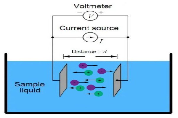
Construction of simple conductivity sensors involves the use of an insulating material embedded with platinum, graphite, stainless steel, or other metallic pieces. Moreover, these metal contacts serve as sensing elements and are placed at a fixed distance apart to make contact with a solution whose conductivity is to be determined. The length between the sensing elements, as well as the surface area of the metallic piece, determine the electrode cell constant, defined as length/area. The cell constant is a critical parameter affecting the conductance value produced by the cell and handled by the electronic circuitry.
Generally, a cell constant of 1.0 will produce a conductance reading approximately equal to the solution conductivity. If a solution has low conductivity, the sensing electrodes can be closer together. Thus, reducing the length between them and producing cell constants of 0.1 or 0.01. As a result, the conductance reading will rise by a factor of 10 to 100 to offset the low solution conductivity and give a better signal to the conductivity meter. On the other hand, the position of sensing electrodes can be farther apart to create cell constants of 10 or 100 for use in highly conductive solutions. This also produces a conductance acceptable to the meter by reducing the conductance reading by a factor of 10 to 100.
In order to produce a measuring signal acceptable to the conductivity meter, it is highly important that the user choose a conductivity electrode with a cell constant appropriate for his sample. The table below lists the optimum conductivity range for cells with different cell constants.
| Cell Constant | Optimum Conductivity Range |
|---|---|
| 0.01 | 0.055 – 20 μS/cm |
| 0.1 | 0.5 – 200 μS/cm |
| 1.0 | 0.01 – 2 mS/cm |
| 10.0 | 1 – 200 mS/cm |
Effects of Polarization
When a DC voltage is applied across the electrodes of a conductivity cell, the ions present in solution will be discharged onto the electrodes. This occurs as the ions change into their molecular form while surrendering or accepting electrons. The flow of ions will then virtually cease within a very short time, and consequently, the current will decrease to virtually zero. Therefore, an AC voltage is preferable for conductivity measurements. Polarization, however, can still actually take place during a half cycle of one polarity, causing a space charge buildup around the electrodes, resulting in a loss of current flow. In addition to polarization effects, conductivity cells with higher cell constants require long, narrow passages to obtain these constants, which make the electrode contacts more susceptible to coating by oils, slurries, or sludges commonly found in streams of high conductivity.
Platinization
Platinization, or depositing a layer of black platinum on the electrode cells, results in a decreased polarization resistance. Moreover, the platinum black catalyzes the electrochemical reaction rate, reducing the current density on the electrode cells and the reduction overvoltage for H+ ions.
How 4-cell Conductivity Probe Eliminates Polarization and Contact Coating Effects
The 4-cell conductivity probe consists of 4 bands along a measuring column or sets of concentric rings opposite each other. By applying an AC voltage across the two outermost bands, current flows through the measuring cell. Located between this pair of electrodes is a second pair of bands, whose function is to measure the voltage generated across the liquid. Then, the measured voltage across the outer bands is compared with the voltage measured by the inner bands.
Any difference between the measured voltages of the two pairs of bands (whether the conductivity of the solution changes or changes due to polarization or coating effects) initiates correcting action for the voltage across the outer bands. The correcting action remains until the current through the cell generates a voltage across the outer bands which equals the voltage between the inner bands. Therefore, the four-band conductivity cell can correct for any fouling or polarization which may occur.
Choice of Conductivity Cell Design: 2-Cell or 4-Cell?
How 2-Cell and 4-Cell Electrodes Compare
| 2-Cell Electrodes Offer: | 4-Cell Electrodes Offer: |
| Reduced cost of purchase and easy maintenance Direct access to cell plates facilitates cleaning. | Improved accuracy over a wide range The improved circuitry eliminates errors due to the polarization effect. Also, analysts achieve accurate calibration with just one standard. |
| Compatibility with sample changers Applications requiring a sampler changer will do better with a 2-electrode cell, because it requires minimal insertion depth – allowing quick readings. | Flexibility for high or low-range measurement One cell and one calibration provide testing capability over several decades of conductivity. |
| Limitation of 2-Cell Electrodes: | Limitation of 4-Cell Electrodes: |
| Measurement Range Accurate conductivity measurement range tops out at about 50 mS/cm. | Critical Minimum Immersion Depth Minimum immersion depth is 3 to 4 cm. |
Operating Instructions
Before use, soak the conductivity electrode in distilled or deionized water for 5 to 10 minutes. Then, connect the conductivity cell to the conductivity meter and follow the meter manual instructions for standardizing the cell for use at a given temperature. Subsequently, rinse the conductivity cell sensing elements with distilled or deionized water between samples. Note: Each conductivity cell has a cell constant predetermined by the manufacturer, which is generally indicated on the electrode upon shipment. The cell constant may change slightly during shipping and storage and should be remeasured on the user’s conductivity meter before initial use. Measure the cell constant according to the meter instruction manual. Because temperature has a large effect on conductivity measurements, allow probe to sit in the solution until a stable temperature reading is obtained before taking measurements.
Cleaning
The single most important requirement of accurate and reproducible results in conductivity measurement is a clean cell. Because, a dirty cell will contaminate the solution and cause the conductivity to change. Also, grease, oil, fingerprints, and other contaminants on the sensing elements can cause erroneous measurements and sporadic responses.
Cleaning Methods
- For most applications, hot water with domestic cleaning detergent can be used for cleaning.
- Whereas, for lime and other hydroxide containing solutions, clean with a 5-10% solution of hydrochloric acid.
- When dealing with solutions containing organic fouling agents (fats, oils, etc.), clean probe with acetone.
- For algae and bacteria-containing solutions, clean probe with a bleach-containing liquid.
Clean cells by dipping or filling the cell with a cleaning solution and agitating for two or three minutes. When a stronger cleaning solution is required, try concentrated hydrochloric acid mixed with 50% isopropanol. Rinse the cell several times with distilled or deionized water and remeasure the cell constant before use.
Storage
It is best to store cells so that the electrodes are immersed in deionized water. Any cell that has been stored dry should be soaked in distilled water for 5 to 10 minutes before use to ensure complete wetting of the electrodes.
Some platinum conductivity cells are coated with platinum black before calibration. This coating is extremely important to cell operation, especially in solutions of high conductivity. Electrodes are platinized to avoid errors due to polarization. Cells should be inspected periodically and after each cleaning. If the black coating appears to be wearing or flaking off the electrodes or if the cell constant has changed by 50%, the cell should be cleaned and the electrodes replatinized.
Replatinizing
The platinum electrode should first be cleaned thoroughly in aqua regia, being careful not to dissolve the platinum. If the cell remains too long in aqua regia, the platinum elements will dissolve completely. Prepare a solution of 0.025 N HCl with 3% chloroplatinic acid (H2PtCl6) and 0.025% lead acetate. Connect the cell to a rheostat or 3-4 V battery to which a variable resistor has been connected. Then, immerse cell in the chloroplatinic acid solution and electrolyze at 10 mA/cm for 10-15 minutes.
Next, reverse the polarity to the cell every 30 seconds until both electrodes are covered with a thin black layer. Disconnect the cell and save the platinizing solution. It may be reused many times and should not be discarded as it is expensive to make. Subsequently, rinse the electrode with tap water for 1 to 2 minutes, followed by distilled or deionized water. Finally, store in distilled or deionized water until ready for use.