AlpHa Measurement Solutions | Reference Electrodes

Reference Electrode: Nature and Role

The reference electrode or “half-cell” is a system that provides a constant defined potential in electrochemical analysis. The accuracy and longevity of the pH or ion measurement system highly depends on the accuracy and stability of the reference electrode, making it an essential and critical design input in the overall system.  

Designing and Selecting a Reference System

The reference design can enable the ability to control the electrolyte leakage rate, electrolyte or fill solution, and sample matrix compatibility options. Because the reference electrode is often the limiting factor regarding the sensing system’s overall life, there are features such as multiple junctions, junction materials, reference electrolyte chemistry, and other design inputs that can prolong the life of the reference system. The electrolyte inherently “leaks” from the reference junction in many of the designs. Controlling that leakage rate and mitigating the leakage of silver ions is another reference electrode strategy. 

For more information regarding the technical background of reference electrodes, please visit our reference electrode article in AlpHa Insights (Insert Link to page). AlpHa’s subject matter experts will help coach and guide the appropriate reference system for the required application. For example, depending on the sample matrix, it is critical to pick the reference type and corresponding salt bridge. The following are reference potentials for common reference systems used globally:

Reference Electrode System

Electrolyte

Potential vs. Standard H2 Electrode (SHE)

Potential vs. Saturated Calomel Electrode (SCE)

Ag / AgCl

Sat. KCl

200 mV

-44 mV

Ag / AgCl

3M KCl

210 mV

-32 mV

Hg / Hg2Cl2 (Calomel) (SCE)

Sat. KCl

244 mV

0 mV

Hg / Hg2Cl2 (Calomel)

Sat. LiCl

200 mV

-45 mV

Hg / HgO 20% KOH / 4.24M 98 mV-143 mV

Hg / Hg2SO4

Sat. K2SO4

640 mV

408 mV

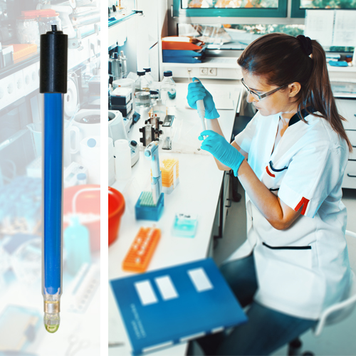
AlpHa continues to develop reference systems for many different applications. This includes Teflon junctions for those applications where rapid changes in pressure can cause issues in other reference systems. AlpHa also developed a unique new Solid-State reference system. Inside the Solid-State reference system, the inner and outer reference chamber liquid gels have been replaced with a solid polymer gel. The reference electrolytes then are non-reactive, non-contaminating, and include high salt content polymer gels. As a result, the Solid-State reference design creates an alternative option when selecting the appropriate reference system. 

Combo vs. Stand-alone Reference Electrode

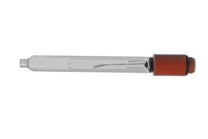
While it is much more common in the industry to combine the reference with the working electrode, there are applications where a stand-alone working and reference electrodes are desired. This is critical when designing for applications that cause the reference to poison or clog prematurely.

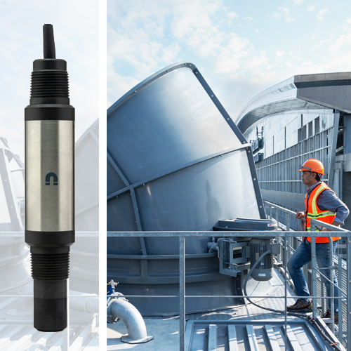
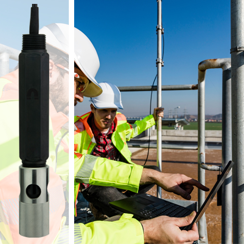
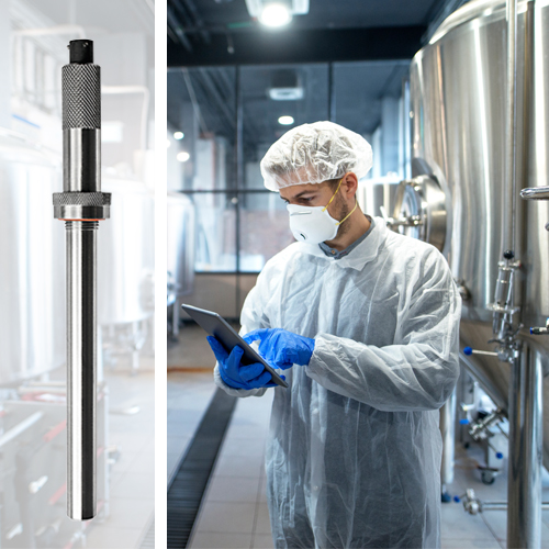
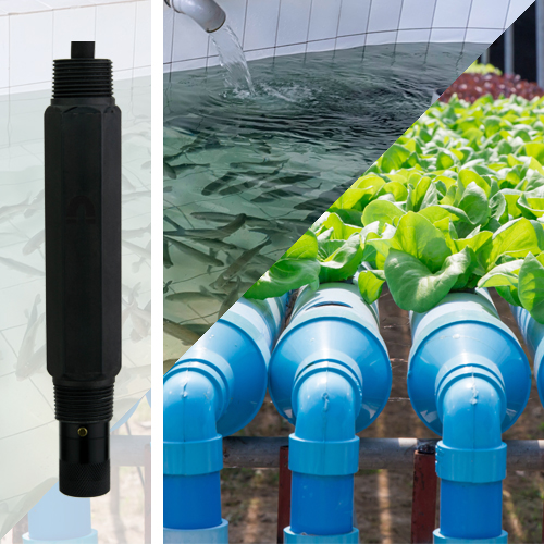
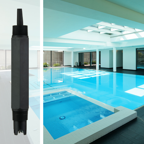
Environmental monitoring applications that require to measure multiple parameters simultaneously often utilizes a shared reference electrode with replaceable or refillable options in the sensor array. For example, pH, ORP and ISE sensing “half-cell” or “mono” electrodes can all share a single reference half-cell in a multiparameter electrode system or sonde. This can optimize the service life of the electrodes where long-term deployment is essential. AlpHa Measurement Solutions designs both customizable stand-alone reference electrodes and combination electrodes for all ranges of applications.

This article aims to educate the user about one of the most important aspects of electrode measurements – Reference Electrodes. They are the source of most difficulties you encounter while performing measurements, and more specifically, the reference electrode’s liquid junction. 

Therefore, a greater knowledge of the role that the reference electrode plays is of great benefit to the user.  We will discuss the various types of reference electrodes and the components which make them up. In addition, we will review their relative strengths and weaknesses to facilitate choosing a suitable reference electrode for your application.

The purpose of a reference electrode is to complete the electrical circuit and provide a stable ground voltage to carry out electrochemical measurements. It achieves this by providing an isolated and stable chemical reaction that produces a predictable voltage value. Effectiveness of a reference electrode is in its ability to produce a stable and reproducible potential for comparison with the indicating electrode potential.

Construction of Reference Electrodes

The typical reference electrode consists of an internal element, normally silver-silver chloride, surrounded by an electrolyte-containing filling solution. Usually, this solution is KCl, saturated with AgCl, inside a glass or plastic body salt bridge, and terminating at the liquid junction.

It is important that the internal element remains wet and surrounded by the reference electrolyte-filling solution.  This is why VLC ships all its reference electrodes pre-filled with reference filling solution.  Moreover, sealing the fill hole with tape or rubber grommet is necessary to prevent leakage of the solution during shipment. Also, removing the seal prior to use is mandatory. Else, as the fill solution leaks out of the liquid junction, there will be a vacuum inside the electrode. This will progress until the fill solution can no longer flow out of the electrode. Thus, leading to drifting or instability of readings.

Shipping our reference electrodes is usually with a cap containing reference fill solution covering the liquid junction.  Like the internal element, it is necessary to keep the liquid junction wet in order for the electrode to function properly.

Liquid Junctions of Reference Electrodes

The liquid junction allows the leakage of reference electrolyte filling solution into the sample. As a result, it completes the electrical circuit needed for potentiometric measurements.  VLC can manufacture reference electrodes in various configurations and from various materials.  There are a variety of liquid junction styles and materials to choose from.  Keep in mind that there is no “universal” liquid junction. The difference between the various junction types is mainly the potential that each liquid junction-sample interface generates. Another difference is the flow rate of the reference filling solution through the liquid junction into the sample.  The choice of liquid junction type is mostly application dependent.

There are two basic classes of liquid junctions.  The first is a “flowing” junction.  This class of liquid junction allows the electrolyte in its entirety (liquid/gel and all) to make contact with the sample through the junction (see Glass Sleeve and Open Aperture examples below).  Liquid junctions of this type have moderate to high flow rates. Also, they provide low resistance and low junction potentials, but have a higher degree of sample contamination. 

The second class of liquid junctions is a “Diffusion” junction (see Annular Ceramic, Ceramic Wick, and Teflon examples below).  This class allows only the ions of the electrolyte to pass through the junction and into the test sample. Diffusion-type liquid junctions exhibit lower flow rates and less sample contamination but easily clog. The table in the next section describes the various reference liquid junctions Alpha offers and other key details.

Reference Liquid Junction Offerings from Alpha

Alpha Liquid Junction Diagram Description
Annular Ceramic Making an annular ceramic junction involves wedging a thin layer of ceramic between the outer body and inner body of the reference chamber.  The ceramic itself has a small pore size, therefor it exhibits a low flow rate, extending the time between refilling of the reference electrolyte. This type of liquid junction are suitable for most general laboratory-type applications. The principle drawback of this style is that the liquid junction itself is difficult to clean on contamination.  Careful selection of the reference electrolyte can help reduce/eliminate the fouling effect.
Ceramic Wick A ceramic wick junction entails inserting a ceramic wick (also called a frit) through the tip/end of the reference chamber.  Also, it shares many characteristics with the annular ceramic-style liquid junction.  It has a small pore size (although various pore sizes are available upon special request), and therefore, a slow flow rate.  This liquid junction type also is difficult to clean.  Again, careful selection of the reference electrolyte can help mitigate/eliminate the fouling effect.
P.T.F.E. (Teflon) Making this liquid junction involves press-fitting a plug of Teflon into the tip of the reference electrode.  Teflon is a very versatile liquid junction material, as it can serve in either a flowing reference design (with a liquid reference electrolyte, such as in laboratory-style electrodes), or in a diffusion-style liquid junction (with a gelled electrolyte).  This type of liquid junction is common in industrial application electrodes.  When combined with a polymer gel reference electrolyte, the hydrophobic nature of Teflon helps prevent contamination of the liquid junction. While its large pore size makes for low junction potentials, and the ability to more rapidly equilibrate to pressure changes in those applications where the environment is dynamic in nature.
Glass Sleeve This liquid junction type is made by drilling a small hole in the side of the reference electrode.  A movable, tapered ground glass “sleeve” envelopes the outer body of the reference electrode.  This sleeve can be moved up the electrode body to fully expose the hole, allowing quick draining of the reference electrolyte for cleaning, and moved down to cover the hole for operational use.  This style of liquid junction exhibits an extremely high flow rate. As such, it offers highly stable and very low junction potentials.  The very fast flow rate of these types of reference electrodes requires frequent refilling of the reference electrolyte, and as such, sample contamination may be of concern for certain applications.  This style of reference electrodes is generally found in laboratory applications, where accuracy is paramount.
Open Aperture This liquid junction is made by simply drilling a hole in the side of the reference electrode.  Its reference electrolyte must be gelled in some fashion to prevent overly rapid depletion of the reference electrolyte.  This gel is completely exposed to the sample.  The open aperture style liquid junction is typically used in applications having high solids content and in suspensions/emulsions.  It is also beneficial in the monitoring of precipitation reactions, which can easily clog/foul other liquid junction styles which have a physical, porous salt bridge.
Liquid Junctions Offerings from Alpha

Contamination Effects

As stated earlier, the Silver-Silver chloride reference element is the reference element of choice. This goes with a potassium chloride solution saturated with Silver chloride used as the reference electrolyte fill. Moreover, the KCl solution is saturated with AgCl. Thus, preventing incidental stripping of the AgCl from the Silver wire (the reference internal element) to dissolve into the KCl reference electrolyte solution.

But what do we do if the sample we wish to test would become contaminated by contacting Silver ions? For example, in the food industry. Or what if the sample contains silver ions, and we want to avoid exposure to a reference electrolyte containing chloride ions?

Double Junction Reference Electrode

This problem is solved by adding a second salt bridge, or junction to the reference electrode. Thereby insulating the inner Silver-Silver chloride reference element from the sample.  This secondary salt bridge can then be filled with a reference electrolyte solution, which does not contain a contaminant to the sample. For a sample containing silver ions, one might choose a saturated Potassium nitrate (KNO3) solution as the reference electrolyte.

Side Arm Reference with Fill Solution Reservoir

Contamination of the internal reference element by the sample is also possible. This occurs if the level of the reference electrode’s filling solution is not properly maintained. The desired flow of filling solution from the reference chamber into the sample is only possible if there is a positive head pressure. Meaning that the level of filling solution must be higher than that of the sample.  If the sample level is higher than that of the level of the reference filling solution, the normal direction of flow can reverse. Thereby making the sample flow into the reference chamber. 

At the minimum, this can result in the formation of unstable potentials.  Extended sample exposure to the internal reference element can lead to contamination/fouling of the internal reference element.  If this happens, the reference electrode must be replaced. For this reason, VLC offers reference electrodes with a built-in sidearm, that maintains positive head pressure requirements for proper functioning. The image to below shows how one can connect a reservoir, filled with reference electrolyte filling solution, to the reference electrode to maintain positive head pressure. This setup is common in long-term measurements applications, if daily electrode maintenance is not possible or convenient.

How to connect reference electrodes to reservoir.
Electrode to Reservoir Connection

Liquid Junction Potentials of Reference Electrodes

When a reference electrode is in a sample, a potential develops at the junction of the reference filling solution and sample. This is the liquid junction potential. It develops because of the difference in composition between the reference fill solution and the sample.  The liquid junction design allows the interdiffusion of ions between the reference filling solution and the sample.  However, different ions diffuse at varying rates, so the electrical charge they carry will move unequally across the junction.  Hence, the formation of the reference junction potential.  We can control the magnitude and stability of this potential by careful selecting the liquid junction material and filling solution.

The table of liquid junction offerings from Alpha serves as a guide as to which junction material type is appropriate for your application.  The next section will discuss in more detail our choice of reference fill solution.

Reference Filling Solutions

The ideal reference-filling solution for any particular application should meet the following requirements:

We have already mentioned an example of the 1st requirement – the typical reference filling solution of KCl reacting with a sample containing Silver to form silver chloride.  The second requirement is readily accomplished by simply making the fill solution either saturated or sufficiently concentrated with the electrolyte of choice.  The third requirement requires choosing a reference fill solution whose electrolyte provides equal transference of the positive and negative charges moving across the liquid junction.

The ability of an ion to carry an electrical charge is related to its ionic equivalent conductance (λ0, mho-cm/equivalent/liter).  Below is a table of varying ions and their equivalent conductance in various solutions.

Limiting Equivalent Conductance

Cations Aqueous Methanol Ethanol
Ag+ 61.9 17.9
Ba+2 63.6 62.0
Ca+2 59.5 61.0
Cu+2 53.6
H+ 349.8 141.8 57.4
K+ 73.5 52.4 22.0
Li+ 38.7 39.8 15.0
Mg+2 53.1 59.0
Na+2 50.1 45.9 18.9
NH4+ 73.5 57.9 19.6
(CH3)4N+ 44.9 70.1 28.3
(C2H5)(CH3)3N+ 40.8
(C4Hg)(CH3)3N+ 33.6
(C2H5)4N+ 32.7 60.4 27.8
(C3H7)4N+ 23.4 46.1
(n-C4H9)4N+ 19.5 39.1
Anions
Br 78.14 56.4 26.0
Cl 76.4 51.2 24.3
CO3-2 69.3
ClO4 67.3 70.1 33.5
F 55.4
HCO3 44.5
I 76.8 62.7 28.8
NO3 71.4 60.5 28.0
OH 198.6
SO4-2 80.0
SCN 66.0 60.8 29.7
Acetate 40.9 53.0
Benzoate 32.4    
N-Butyrate 32.6    
Oxalate-2 74.2    
Picrate 30.4 47.0 26.3
Propionte 35.8 21.0
* From Parsons, “Handbook of Electrochemical Constants,” Butterworth, London, 1959, and L. Meites, “Handbook of Analytical Chemistry,” McGraw-Hill, New York, 1973.
Limiting Equivalent Conductance of Ions

Looking at this table, one can see why KCl is a very popular reference electrolyte fill solution.  Potassium has a limiting equivalent conductance of 73.5, while Chloride has a limiting equivalent conductance of 76.4.  Take note of the limiting equivalent conductance values for H+ and OH.  They are much higher than the values for most other ions.  This is what makes achieving equitransference in strong acids and strong bases difficult. Making it often the cause for the long response times encountered when measuring these samples.

Effects of changing the reference fill solution

After changing a reference electrode’s filling solution, the potential at the fill solution-internal reference element interface changes as well.  This new potential may be less stable and/or more sensitive to temperature changes than the previous fill solution. So, it is important to take note of response times when using a new reference fill solution.  Also, this new potential takes time to establish itself, so it is good practice to allow the setup stand overnight. This is why most people do not change out the reference fill solution. Rather, they simply purchase separate reference electrodes, with each reference electrode having a single reference fill solution.

Crystallization of Reference Electrodes

Regular users of reference electrodes often encounter the formation of crystals at the bottom end of their electrodes. These are simply the salt crystals of the electrolyte solution of the reference electrode.  To novice users, however, this at first may seem to be some form of contamination, but it is not.  Most reference electrolyte filling solutions are saturated salt solutions.  For reasons such as water evaporating from the fill solution or temperature drop, these salts fall out of the solution. Then, they form crystals, which naturally settles to the bottom of the electrode.  These salt crystals will not, up to a point, interfere with the electrode’s performance.  The crystals, actually serve a purpose to us.  They ensure the filling solution maintains saturation. 

However, over time, these crystals can become packed together tightly and obstruct the flow of reference-filling solution through the junction.  Resolving this involves draining the reference electrode of its reference fill solution and refilling it with distilled water.  This allows the salt crystals to dissolve into the distilled water, before putting in a new reference filling solution.  Note, sometimes, rinsing several times with distilled water may be necessary to dissolve all the crystals.

Cleaning/Unclogging a Liquid Junction

Your liquid junction likely needs unclogging if readings are drifty, jumpy, or require a long stabilization time.  The first cleaning method to try is the same as that in the crystallization section above.  Simply drain the electrode of the fill solution, rinse it several times with distilled water, and refill the filling solution.  If this doesn’t improve the performance of the electrode, you can next try pulling a vacuum over the liquid junction (typically located at the tip of the electrode) to try and force the filling solution through the liquid junction.  If your liquid junction still needs unclogging, then it is necessary to take more severe steps. 

The next step is to boil the liquid junction in a dilute KCl solution for 10 minutes.  Then, turn off the heat and allow the electrode to cool while immersed in the solution before resuming testing.  The last step to try, if boiling is unsuccessful, is the physical, abrasive cleaning of the liquid junction itself.  Place a piece of #600 Emory paper on a flat surface and place a drop of water on the Emory paper.  Placing the liquid junction perpendicular to the paper, rotate it in a circular fashion against the paper.  Note, this cleaning method should be only as a last resort. Because, sanding the liquid junction will severely shorten the life of the reference electrode.